The basic components of a mechanical system combined with Vision.
For a basic Vision system, cameras, lenses and lighting are indispensable. Furthermore, for Vision to operate accurately, effectively and flexibly in industrial production, it is necessary to combine with mechanical systems. There is a folk saying "A sharp knife is not as good as a solid foundation" to express the importance of mechanical systems.
Some applications of mechanical systems when combined with Vision are:
Transmission, control: moving structural components, system control mechanisms
Workpiece control mechanism: workpiece handling system, workpiece feeding/discharging
Inspection, measurement: positioning/clamping system, assembly/processing, collection/classification
Some mechanical components are often combined with Vision such as conveyor systems, pneumatic cylinders, sensors, probes, etc. To better understand how these components will be selected and designed, let's take a look at some commonly used mechanical systems combined with Vision below.
1. Workpiece position adjustment system
Application: Moving, controlling workpiece position, workpiece feeding system, inspection or measurement
Purpose: Perform visual inspection of mechanical components
Workpiece used: Plastic gears with a diameter of 34mm, height of 29mm
.png)
Workpiece Positioning System Model
The system uses a workpiece positioning method: The workpiece on the worktable is positioned from two directions for the clamping unit to avoid affecting the machining guide. This allows the clamping claws to clamp the workpiece near the center of gravity
Notes on selecting mechanical components:
Select a camera lens from the inspection resolution requirements: CCTV Lens - The lens is mounted on the camera to inspect the product, based on the change of the camera, the fault, the inspection requirements and the testing to select the appropriate lens.
Select the DIA cylinder from the load condition, the cylinder with the guide and the air slide are used to move the components under the guide. suitable for workpiece lifting motion source, pay attention to speed
If the component is unstable in the lifting position, add a component position recognition sensor, to enable safer transportation
When designing, pay special attention to the size, part distance and operating speed of the system and give a specific number. For this design, the design is 50% more compact than the conventional guide cylinder design.
.JPG)
Some mechanical components used
Design specifications:
- Overall height: 341 mm
- External dimensions: 320 x 320 x 341 mm
- Up/down stroke: 30 mm
- Feed stroke: 50 mm
- Component feed position accuracy: ± 0.5
2. Product inspection and classification system that meets/fails to meet standards
Application: Feeding, inspection, classification and measurement
Purpose: Feeding through the conveyor, inspecting and classifying defective products
Blanks: disc-shaped products, diameter 13mm, height 3mm, weight 3.1g
Main components: conveyor, camera, pneumatic cylinder
Operation: The blanks are fed by the operator through the chute and then move down the inspection conveyor, the defective products will be blown off the conveyor through the pneumatic cylinder system.
.png)
Inspection and sorting system model
The workpiece is fed one by one down the conveyor by the roller. The components can be fed evenly through the cutting edge by the roller to help sort the components.
System working principle:
The product is fed by the conveyor through the object detection sensor. The object detection sensor can usually be placed close to the camera position. In case of a timer, the camera position can be customized. If in case of using the Hard-trigger of the camera, the delay of the camera trigger pulse can be adjusted in the camera setting configuration. The software will collect the image and analyze the image to give the output corresponding to the quality of the object. If NG, the object blowing cylinder will be activated to push the object into the NG tray. The OK object will move to the OK tray.
Note on the selection of components:
Camera and LED lighting can be adjusted independently by a single axis, select the appropriate light for the inspection camera to detect basic defects on the product. The speed of the LED needs to be calculated in accordance with the speed of the conveyor.
Use urethane rollers to avoid damaging the workpiece, pay attention to the speed
Guide rails and rollers are provided for the charging chute to feed the workpieces when they are added horizontally.
Determine the angle for feeding the workpieces at which each workpiece can be loaded onto the conveyor by trial and error.
Check the emission of defective workpieces by blowing air to operate normally as intended by adjusting the nozzle and air pressure, through the trace and error
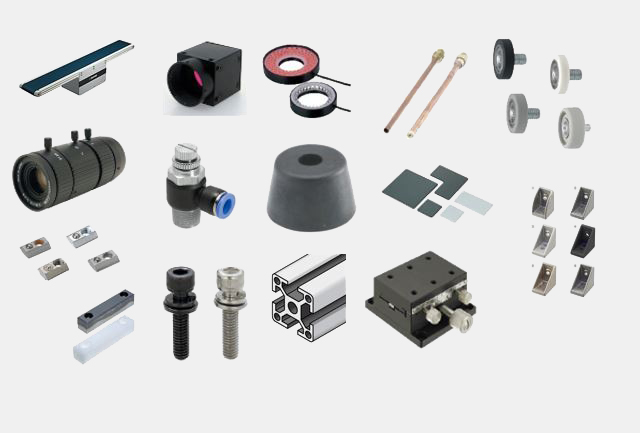
Some mechanical components used
Design specifications:
Conveyor belt: low transmission power (6W), conveyor belt length: 500mm, conveyor belt speed: 18.8m/min
Proximity sensor: can detect the workpiece at a relatively long distance. Detection distance: 14mm ± 10%, distance setting: 0 - 11.2mm, here the distance between the proximity sensor and the workpiece is set to 6.1mm
Outside dimensions: W650 x D250 x H437 mm
3. Electrical characteristics testing system using contact probe
Application: Conveying, moving, testing and measuring
Purpose: Fixture for testing electrical characteristics using contact probe
Workpiece used: Small PC board W22xD26xt1mm
Operating: The workpiece is placed on the robot fixed table, and then slides into position under the probe for testing
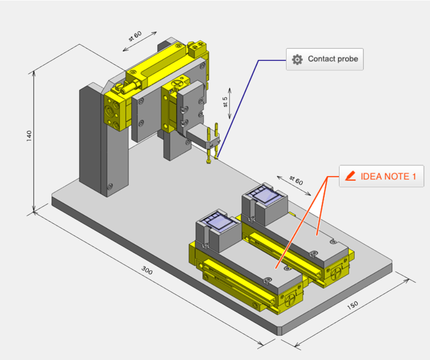
Electrical properties testing system model using contact probes
Two load tables will balance the operation time. Electrical properties testing takes more time than loading and positioning the workpiece. Two process tables where the workpiece can be loaded alternately, with the probe table moving, balance the cycle time.
Notes on the selection of mechanical components:
Pneumatic linear guide. Compared with a typical cylinder with a guide, the pneumatic guide has a more compact design (two times smaller cross-section). When using a pneumatic linear guide, set the side that requires higher accuracy as the stop side.
Select a contact probe that matches the material of the workpiece being tested.
Contact probe: To test the conductivity of the workpiece. The shape of the contact tip depends on the test object. Disadvantages may be wire breakage, deformation.
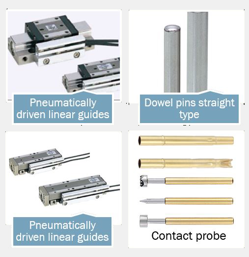
Some mechanical parts used
Design specifications:
Outside dimensions: W150 x D300 x H140mm
Positioning accuracy: ± 0.3mm
4. Pick and Place System (Suction Cup Head)
Application: Conveying and moving
Purpose: Pick and place moving with suction holder
Workpiece used: Plastic disc diameter 84mm, height 13mm, mass 20g
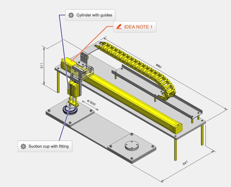
Model of the receiving and checking system
Reduce design steps with the combination of components available on the market Aim to reduce design steps by structuring the main mechanism with the combination of components available on the market
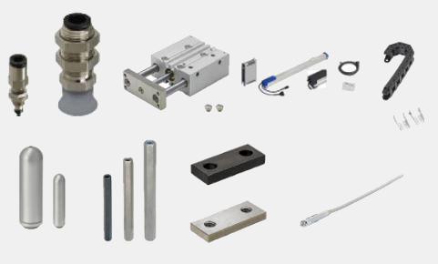
Notes when selecting components:
Choose a suitable suction holder to suck the workpiece and the robot meets the transfer specifications (Load, speed, stroke). For longer strokes, use a cable holder to avoid tangling or damage to the harness. Due to the deterioration of the suction cup, including the pressure switch to monitor the contact, also perform periodic maintenance to avoid loss of suction.
Articulated suction cup: Suitable for clamping flat surfaces of workpieces, the disadvantage is that it may lose its suction ability due to wear and deterioration
Guideline cylinder: For ease of design, this was chosen as it is a complete assembly without the need for additional design
Single axis robots are used as multiple positions are required in a single stroke.