Steps to perform a basic test application
To build a testing application, depending on the complexity of the project, people will use different solutions. However, the most important thing to note is that the chosen solution must be suitable for the requirements of the project. The more flexible the system is, the easier it will be to adapt to new tasks that may occur later, especially in production, there is always room for improvement. Therefore, considering possible future needs should be part of the initial step when building a testing system.
.png)
The diagram above is a simple production inspection process using a smart camera to inspect the nozzle of the sprayer. The system consists of the following main components:
1. Vision module (Camera, lens, lighting) and data processor
2. IO device (PLC, or programmable controller)
3. Product removal mechanical device
4. Object detection sensor
The object detection signal will be sent to the programming controller to control the light and camera trigger signal. The processor after receiving the image will analyze based on the programmed processing functions to evaluate the quality of the object. When detecting NG products, the controller will output a signal to activate the product removal device.
.png)
A more complex inspection system may require multiple cameras to inspect multiple locations. The diagram above shows the lighting controller used to adjust the lighting level at each inspection station.
A simple inspection application typically involves the following steps:
1. Image acquisition
The purpose of this step is to set up the system to get the best image and highlight the defect to be looked for. This may require a combination of specialized lights and filters. It is important to remember that cameras are not as flexible as the human eye, so ambient light alone may not produce the best image. It may also be necessary to adjust some system parameters such as setting the camera trigger time, adjusting the camera exposure to reduce motion blur, or deciding whether to control the lighting. Different from photography in life, industrial photography is to highlight defective (unwanted) objects on products or clarify product boundaries in size inspection.
.JPG)
Optimizing lighting to highlight image objects of interest on the product
2. Locating the inspection location
Once the best image has been obtained, it is also important to locate the object within the image.
The aim here is to have the object in the same position and facing the camera for each inspection as this can simplify the inspection. However, using a mechanical system to do this is ideal. In many applications this is not possible or the mechanical system does not eliminate all movement. To solve this problem, the first step is to locate a part within the image.
This is often referred to as creating a fixed point or anchor point and usually involves finding two edges or two patterns on the item, so that all further inspection tools can be referenced to this feature. Depending on the size of the intended area, additional time may be required to accurately position the object.
.JPG)
The object's dimension can be determined through the white box inside the image of the object
3. Inspection
Once the best image has been obtained, the location has been determined to simplify the inspection, and the inspection tools will be applied. Depending on the complexity of the inspection stage, the inspection time can vary significantly. The tools provided in the inspection software: color, Blob, dimension measurement, edge and area search (Edge and Area Searching) allow engineers to be flexible in building product inspection applications
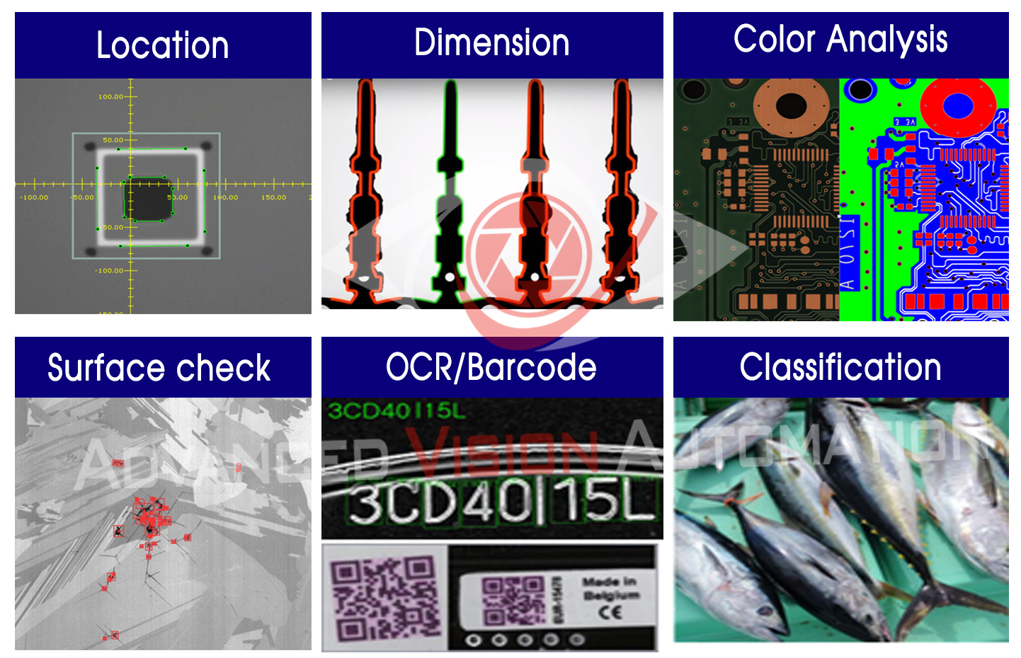
AVA Vision Industrial Inspection Application Building Tools
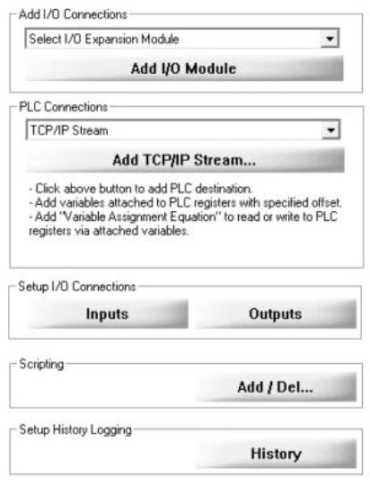
4. Final Results and Connectivity
The final results are generated after all results from the deployed tools have been evaluated. Once the results are known, the pass/fail level can be set to an appropriate level or in some applications this reject output needs to be synchronized to work as the product moves down the production line. Most modern vision systems today support the same Ethernet control standards as the PLC, such as Ethernet IP, so that results and status can be directly linked to the PLC card allowing tight integration between the vision system and the PLC.