Important factors when selecting components for machine vision systems
Ngày: 18/11/2020
Choosing a camera for a machine vision system is not simply a matter of choosing a camera, but also a lot of factors that need to be considered to produce quality images and optimize them for easy programming. The first three concerns are:
1. Choosing the sensor type and resolution based on the application needs
2. How to choose the best camera and optics to meet the requirements
3. Combining the right lighting to highlight features for higher inspection reliability
.JPG)
Some of the widespread applications of machine vision: Code reading, color inspection, product surface inspection, product assembly inspection, robot guidance and dimension measurement
Image quality is really the key factor in the operation of the machine, it reflects the real efficiency of the inspection system so it is necessary to get the best quality image possible. It is necessary to choose a CMOS or CCD sensor when knowing the type of lens, the working distance of the lens when focusing (WD: Working distance) and creating uniform light to highlight the objects you want to inspect, reducing anything in the background that you are not interested in. Machine vision is commonly used in: reading 2D code, measuring, measuring angular distance, detecting defects, determining coordinates, searching for colors, verifying assembly, ...
.JPG)
Some cameras and sensors (CMOS, CCD)
The choice of camera sensor depends on the application you are looking for (related to the characteristics of the inspection object), the required accuracy (or the smallest size of the defect on the object), how fast the acquisition is, the actual environment, whether you are using a color or monochrome camera, an area camera or a line scan camera. Determining exactly what you are looking for in terms of defect detection, distance measurement, barcode reading or OCR reading, etc. is also an important issue in choosing a camera for your application.
To achieve the desired accuracy, you first need to determine the most suitable FOV. FOV (Field of View) is the field of view, indicating how much of the image can be captured through the camera and lens you are using. FOV changes as the focal length of the lens and the size of the sensor (or film size) change. Then determine the optimal working range, the accuracy to be achieved, how many cameras to use and whether the system can achieve better results than designed.
#1 Defect inspection application: The size of the defect compared to the inspection object must occupy at least 3-4 pixels on the acquired image
For example: FOV = 12”, minimum object size = 0.25”
(FOV/defect size)x(min# of pixels)
12/0.25x3=144 pixels (camera 640)
#2 Measurement and Pick-n-Place application
For example: FOV = 2”, accuracy = 0.01”
(FOV/sensor size) = inches/pixel
2/640 = 0.0031 inches
2/1280 = 0.001 inches
.JPG)
Increase your accuracy by reducing the FOV with two cameras
Using a color camera or a monochrome camera, the question is do you really need a color camera, are you looking for the presence of a color or can this application be done with a monochrome camera? Because in fact, many applications do not necessarily need to use a color camera, even when using a monochrome camera, the results are clearer. Especially note, if using a color camera you must use white light and must white balance when shooting.
.JPG)
Usually, most applications in practice are moving or require speed to ensure work efficiency. Therefore, speed also affects the system to a large extent. The total test time is equal to the time the camera takes to capture images and process them.
For example: 30 fps = 1800 ppm
297 fps = 17 820 ppm
Electronic shutter: needs enough light - microseconds
Strobe: 300 + PPM
Working environment in food area, wet with oil, high/low temperature or vibration is also worth noting when choosing equipment to use. For example, in food environment, to ensure safety and cleanliness standards, if in wet area, people will wash all equipment with chlorine mixture, acid or various chemicals that will corrode aluminum steel, so you will need things like stainless steel in plastic or rubber housing, using IP67 standard camera. Or in dusty environment, one of the necessary things is to protect the camera and lens from dust, splashing materials that cause image quality to decrease. In high temperature environment, cool the camera, do not let condensation inside the camera place to blur the camera. Most products will move, so the camera should be fixed to a type of bracket, avoid large impacts, can be combined with concrete structure to prevent vibration.
.JPG)
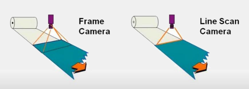
Some customers are looking for maybe a tear on the edge or some defect that happens, or a hole,…so that they can easily detect it, they use multiple area cameras. However, in the case where the customer wants to find very small defects, especially on the film where you see micro holes or stains, in this case the line scan camera will do better.
Select a line scan camera
-
The line scan camera is selected according to the sensor size and line speed
-
Determine the sensor size (the defect size on the inspection object occupies at least 3-4 pixels)
Example: FOV = 12”, defect size = 0.005”
(FOV/defect size)x(min# of pixels)
12/0.005 x 3 = 7200 pixels (8K camera or two 4K cameras)
-
To determine the line speed the camera needs, the image pixel size and the part speed are needed
Example: FOV = 12”, speed 20”/second, 8k camera
Image Pixel size = FOV/ sensor size
12/8192 = 0.001465”
Minimum line speed needed: 20/0.001465 = 13,654
Use a Piranha2 8khz camera ( or 2 Spyder3 4k 18khz cameras)
Some requirements when reading 1D, 2D barcodes or reading OCR text
-
To read 1D barcodes, use an FOV with at least 3+ pixels per bar
-
To read 2D barcodes, use an FOV with at least 4x4 pixels per cell
-
To read OCR text, use an FOV that gives you at least 20x20 pixels on the object
.JPG)
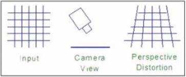
Lens distortion and resolution
- We recommend using good quality “machine vision”, “megapixel” or dedicated lenses: lens resolution can be a limiting factor
- Lens distortion must be compensated for when measuring with a vision system: usually more barrels at shorter focal lengths
In my opinion:
- Parts with depth can have 1/Z “distortion” and depth of field issues: complicates measurements, machine vision is much easier on flat or near flat parts
- Machine vision can measure depth: triangulation, moire, interference,.., quite difficult or impossible to see holes
- Try to position the camera perpendicular to a part
Lens Vignetting
- Effective thickness of the iris reduces light at the edges proportional to cos^4(i)
- Sensor typically uses only the center of the lens
- Worse at short focal lengths – spot correction filters
.JPG)
Telecentric Lenses
- Low distortion and optical vignette
- Recommended for precision measurements
- Very little perspective distortion
- FOV is the diameter of the lens
- Still limited depth of field
- Price of machine vision lenses is 4 to 15 times higher
It can be said that lighting is also one of the important factors affecting the quality of the image. The image below is an example of shooting the same subject but using different types of light.
.JPG)
Some points to note when setting up a lighting system for a vision system:
- Maintain constant light, not changing over time
- Maintain consistent light, illuminating without creating bright spots or shadows
- Prevent changes in the environment's lighting
- Optimize contrast
- Separate important features or elements from the background
- Choose the appropriate light source for the type of inspection you want to perform
Lighting techniques:
- Backlight (Transmitted) – Facing the camera
- Incident (Reflected) – On the same side as the camera
General Purpose – Ring or Area
DOAL – Diffused On-Axis Light
DOME, CDI, SCDI – Diffused, Uniform Light
Dark-Field – Low-Angle Illumination “W”
- Colored light and infrared light
.JPG)
Backlight
- Checking Contours
- Transmitted vs. Blocked Light
- Locating and Measuring External Dimensions
- Highlighting the Internal Structure of Transparent Objects
.JPG)
Ring Lights
- Even illumination from all sides reduces shadows
- Center light on image
- Emphasizes surface features on non-reflective parts
- Low angle ring lights emphasize edges and scratches on shiny surfaces
- Illuminate flat diffused surfaces
.JPG)
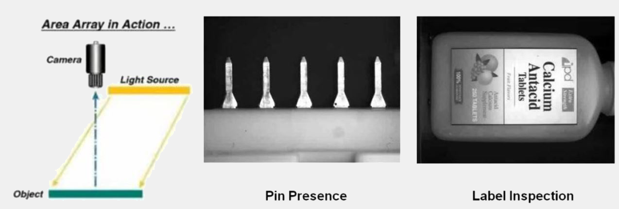
Area Array Lights
- General purpose unidirectional lighting
- Good for applications with non-reflective surfaces
- Economical
- Can be used in a variety of configurations
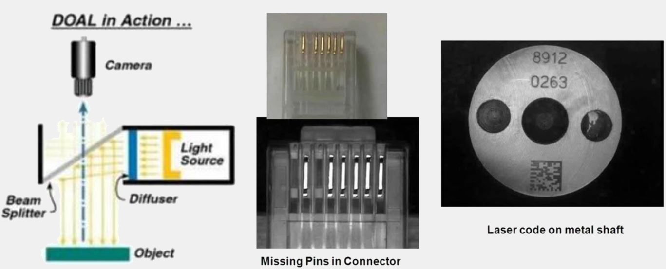
Diffused On-Axis Lights
- Even, diffuse illumination for flat, reflective surfaces
- Greater uniformity than conventional sources
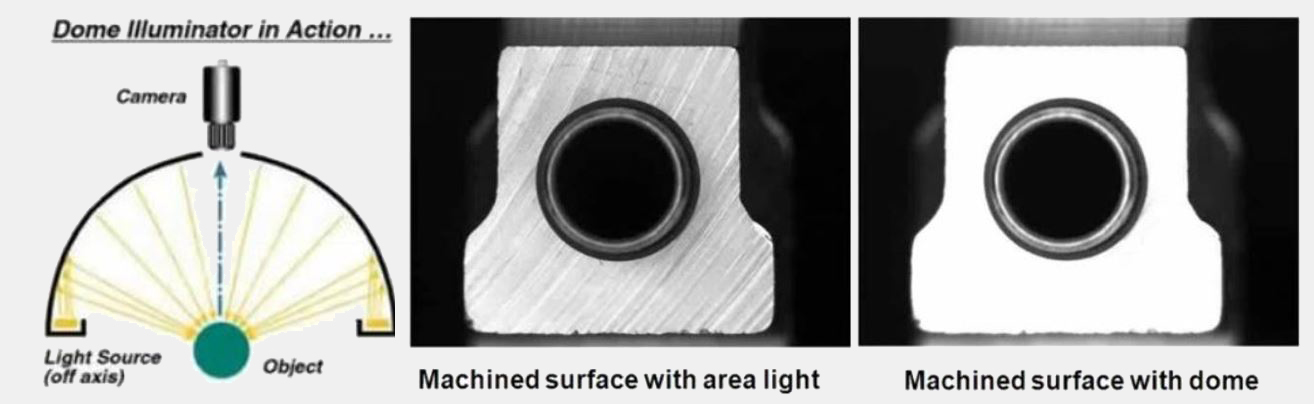
Dome
- Extremely uniform diffused lighting
- Practical solution for shiny, uneven surfaces
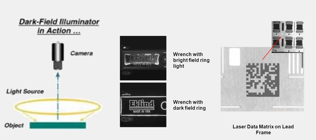
Dark-Field
- Low-angle lighting to highlight irregularities of a surface section
- Emphasizes “enhanced” features
Colored and Infrared Light
Using colored lights to create contrast
- The same light spectrum will make one part appear brighter (i.e. a red LED will highlight red)
- Opposite light spectrums will make one part appear darker (i.e. a red LED will make green objects darker)
Infrared light sources fake grayscale differences between multicolored objects
- Note: Black absorbs infrared
Thus, machine vision is the key technology to improving product quality and productivity. To build an effective machine vision system in a factory, you need to:
- Determine the task you want the machine vision to perform
- Choose the combination of camera resolution, lens, and lighting
- Understand the performance criteria and limitations of the technology you choose
- Choose a solution that meets your current and long-term needs